Home

ELECTROSTAR KITS

On My Workbench

Pictures 1

Pictures 2

Pictures 3

Night Shots

Aerial Photographs

Description

Loco Fleet

Wagons

Visitors Stock

Other Stock

DCC

Exhibitions

Magazine Articles

Model Rail October 2004

DEMU UPDate Issue 39

Trains Online Magazine June '05

Rail Express July 2005

Model Rail September 2005

DEMU UPDate Issue 42

DEMU UPDate Issue 43

DEMU UPDate Issue 46

Making Transfers

Loftus Road

Items For Sale

Links

Email


Copyright © 2005-2012
James Makin
Wells Green TMD

Diesel and Electric Modellers United UPDate Magazine Issue 46

Genetically Modified 'GM's: The low-emission '66's

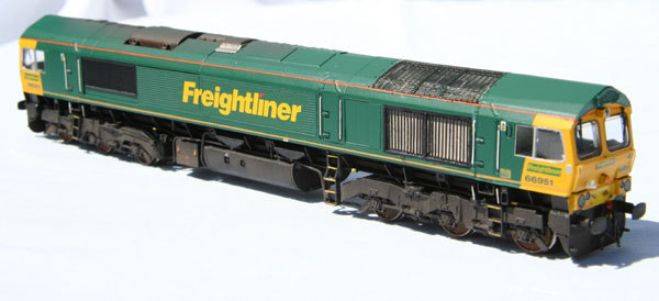
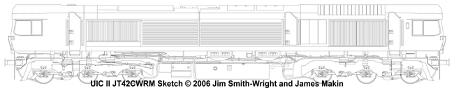
The introduction of the UIC II (International Union of Railways) Leaflet 624 in 2000 recommended diesel traction engine emissions were to be controlled, requiring all traction engines used in new rolling stock and replacement in existing vehicles to comply.

Because of this, General Motors were forced to modify their successful JT42CWR – Class 66 – design, in favour of a more environmentally friendly locomotive. In order to meet the limits of UIC II, the 12-cylinder engine underwent many changes to the cooling system, which restricted access to the engine room, resulting in the third bodyside door being added on one side of the locomotive only. Now classified JT42CWRM, GM Electro-motive Division began offering the low-emission compliant locomotives on 1st January 2003.

Freightliner was the first recipient of the modified ‘66’s, with 66952 arrived in the UK in April 2004, followed by 66951 in October of that year.
Since then, both GBRf and DRS have taken delivery of a batch, and Freightliner has ordered another 16, meaning that the GM “shed” design will be with us for some time yet.

Apart from the fifth bodyside door, there are a number of detail differences affecting modellers wishing to recreate the low emission locomotives.

Here is a summary of the work carried out on the 4mm scale Bachmann model:

  • Addition of the third bodyside door and steps
  • Shortening the fuel tank
  • Moving the roof grille and increasing the width
  • Replacing the existing bodyside grilles with taller and narrower replacements
  • Scribing the new panel lines on the body
  • Altering the roof profile towards the centre of the locomotive
  • Scratchbuilding new cab window quarterlights
  • Underframe detailing, including adding sandpipes
  • Full repaint into Freightliner livery
  • And finally, a light weathering

Adding that extra door
Sourcing the third bodyside door was one of the main challenges of the project, in particular making the decision as to which method to use. By far the cheapest method would be to scratchbuild the door from Plasticard, simply carving the details in with a scalpel.
Unfortunately I was not confident enough to guarantee that my effort would match the fine Bachmann mouldings, so this wasn’t my preferred option. Using a Lima ‘66’ door from an old model was similarly discounted, because of variations in the depth and quality of the grooves and door handles.
Coincidently, at this time I had also purchased another Bachmann class 66, for a class 59 remotoring project.

This meant I had a spare class 66 bodyshell which was soon butchered, extracting the required door. Be careful to cut the correct door from the body – the type with the handles on the left hand side, and ensure the handrails are still attached to the moulding. I chose to remove an entire rectangle of plastic from the donor bodyshell, rather than chopping round the complex angles of the door and rain strip.

The fifth bodyside door is of reduced height compared to the end ones, necessitating the Bachmann door to have approximately 3mm removed from the bottom, resulting in a total height measurement of 16.5mm from the base of the door to the height of the first roof angle. 

Footsteps
The steps below the door proved to be quite a problem – in that a balance of strength vs. realism had to be made. Framework for the steps was created using 40 thou brass wire, drilled upwards into the metal chassis block, providing maximum durability and strength. The wire was bent to match the contour of the steps, bending around the side of the bogie. On my model, the lowest step protrudes 19mm down from the chassis block.
On a class 66, there are two differing designs of bogie footsteps, a shorter smaller design and a taller, thinner design. Bachmann’s moulding of the shorter version came in handy here – this being glued to the lowest point possible on the metal framework, and represents the bottom part of the steps, before they bend around the bogie. The upper, angled part of the steps was scratchbuilt using 0.5mm styrene strip, carefully glued together.
This method should give you a set of steps which look realistic, yet withstand rough handling and are difficult to bend.

Fuel tank modifications
Due to the increased weight of the coolant system and revised engine, fuel capacity on the low-emission compliant machines has been reduced to 5150 litres – resulting in smaller fuel tanks and a more spacious underframe compared with that of a standard ‘66’. Modelling this entailed removing the Bachmann plastic moulding, complete with internal metal block, housing the day/night lighting switch.
On the prototype, the fuel filler caps are closer to the battery boxes than the original GMs, and this requires the tank moulding to be modified, as well as shortened in length.

From the inside, begin removing the vertical plastic outer ends of the tank, cut from inside so that you are left with a battery box attached to a vertical curved end and a single end.
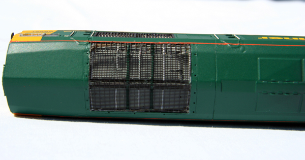
Allowing for the 1.5mm thickness of the vertical ends, cut the large middle section of the fuel tank down in length to 42mm, removing the plastic from the end furthest from the fuel filler caps.
This results in a final length of 45mm for the main fuel tank, when fully reassembled. However – this time glue the tank in the opposite way to match the prototype’s filler cap arrangement.  Now chop the metal weight to fit inside the smaller tank moulding, and reattach the lighting switch circuit board.

Altering the roof grille
The low emission locomotives sport larger roof radiator grilles, extending in width by approximately 3.5mm down the pitch of the roof on one side only.

In addition to this, from examining many photographs in minute detail, it became apparent that all was not well when comparing my RTR Bachmann ‘66’ with photographs. Something did not look right.
Judging from details on the loco, such as the doors in relation to the grille positioning it appears the entire grille is actually a scale 2mm towards the centre of the locomotive.

Unperturbed by such major modifications, I marked out the position of the new grille, and set about carving away the necessary plastic. The Bachmann moulding underneath the roof etch was cut out and moved to it’s new home 2mm further in, whilst the gaping hole left at one end was filled with car body filler and sanded to shape. The panel lines around the grille were then scribed using a scalpel and the bolt holes drilled out in the correct places around the grille panel.
However, the details underneath the roof etch are not totally correct for a 66/9, which requires the addition of two large beams stretching the whole width of the loco. These are then painted in Freightliner Green.
For the grille extension, I attempted to source similar rectangular etched mesh for the roof via the internet, although there appeared to be a dearth of identical etchings available commercially. Laziness then overtook me and I simply robbed the second donor loco of its roof grille!

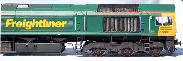
Bodyside grilles & equipment access hatches
Narrower, full-height grilles are fitted to the newer class 66s, stretching right up to the top of the bodyside, aligning with the top height of the cab windows.
On a Bachmann class 66, these grilles measure 36.5mm in width, whereas the low-emission compliant 66s have grilles which scale to approximately 33.5mm.
To convey the impression of depth in the grilles better than Bachmann managed required either;

(a) the use of etches to the correct size, or:
(b) building your own grilles

Having examined available etches such as the conventional class 66 grille from A1 models, it would have been possible to chop this to the correct size using two packets of etched grilles. However, the quality of the grilles leaves a lot to be desired, failing to capture the thin and subtle, angled nature of the louvered grilles.
The latter option of scratchbuilding a grille was initially a daunting prospect, requiring the original grille to be removed and have the edges sanded, leaving a nice smooth cut out measuring 33.5mm x 15.5mm. 20 thou Plasticard was then attached behind the opening, to hide the chassis block. Because of the depth of the plastic bodyshell, you are left with a nice recessed area, almost 2mm deep.
Plastruct MS-30 0.8mm square rod was then used to frame the opening, to provide precise straight edges to the grille cut-out. Two layers of these were required to bring the framing up flush with the bodyside.

To recreate the louvres, I had decided to opt for Slater’s .010x.020 thou microstrip, individually cut and laid onto the grille, using another piece of MS-30 for the central dividing bar. These plastic bars would need to be raised above the Plasticard backing, so two rectangular strips of Plastruct strip were glue at the top and bottom of the grille – providing a suitable base on which to stick the louvres.
When doing work of this nature, one must balance the demand for prototypical realism against the need for durability. Thirteen Slater’s bars were added each side of the central dividing bar on my model, slightly less than on the prototype. This was due to the necessary thickness of the plastic used. Certainly, metal bars would have been more appropriate, but alas, I did not have any at the time.
Upon completion, it was realised that both grilles had consumed over 70 individual pieces of styrene strip themselves, not taking into account the rest of the loco!

The original GM-EMD design featured a set of slightly-recessed double doors in the bodyside, presumably allowing access to the engine room for maintenance, and these were situated just next to the bodyside radiator grilles. On the modified design, these doors remain adjacent to the grilles, except due to the narrower grille design, the door positioning has moved.

Unfortunately, Bachmann has over accentuated the door recesses, so now is an excellent opportunity to correct this by gently filling in the doors and sanding the area down.
The low-emission ‘66’s now sport a panel split into three equal pieces, each measuring 5.5mm across and 14.2mm in height. Following photographs, this was carefully scribed onto the bodyside, ensuring the height aligns with the top of the bodyside radiator grilles.


Those panel lines
Having completed the bulk of the work required, you should now have a plain ‘66’ which looks vaguely like a low-emission compliant version, but still looks a bit odd. One of the main reasons is that during all the filling and sanding, the trademark General Motors panel lines have either been destroyed or covered in dust, which needs to be removed before the painting stage.

On the right hand side of the fifth bodyside door, there is a panel line which needs to be scribed, stretching across the roof of the loco and back down onto the 2-door side (“boring side”!) of the loco. This should align with the edge of the engine-room access hatches on the “boring side”. I use a scalpel to begin the scribing, but then add increased depth using a needle.

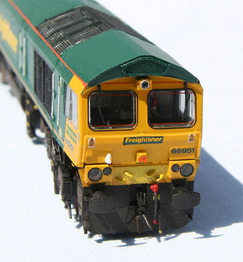
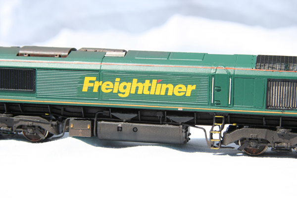
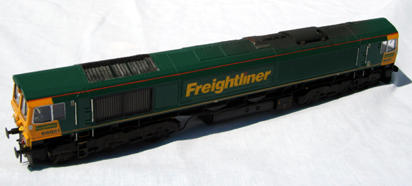
Putting on this panel line then highlights an unforeseen problem. Notice that on the roof between the radiator grille and the four roof access hatches there is a flat capping on the original class 66, measuring 18mm x 5mm.
Compare this to pictures of the low emission 66s, and you will see that this ‘flat top’ needs to be reduced in length to approximately 13.5mm x 5mm. Out with the Plasticard and filler again…

Eventually, after much filling and sanding you should end up with a prototypical UIC II compliant class 66 body, ready for the painting stage. Depending on what locomotive you are modelling will affect how much preparation you have to do to the model. For example, because I used a Freightliner ‘66’ as a donor model and took great care of the ends, it meant I did not need to repaint the yellow, simply requiring a coat of Freightliner Green over the required area.

After application of the green, the roof radiator grille backing received a coat of light grey, whilst the bodyside grille backing was painted in an off-white colour, matched to prototype photographs. One can then start touching in the little details, such as the handrails, cantrail stripes and so on. It is interesting to note that the ‘Freightliner’ logo now stretches over the panel join on the fifth-door side (“the interesting side”!)

New double-glazed single pane cab windows were added to the locomotive, being individually cut from clear plastic sheet, secured in place with Kristal Klear.


Added extras...
Not content with leaving the project there, I set about improving the general look of the model, in a few simple ways.
Firstly, the cab-front lifting eyes were drilled out, vastly improving the ‘face’ of the model, whilst Smiths screw couplings and Replica Railways airpipes were added, too. Pieces of fuse wire were also bent to shape to replicate the prominent sandpipes of the prototype.

However, something I’ve not read about anywhere before is how to actually model the bogie dampers and suspension, something which Bachmann have omitted presumably due to the need for good performance around tight radius pointwork.
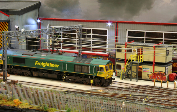
Studying the prototype ‘66’s will reveal just how visible the dampers really are – and I sought to model these, whilst still allowing the locomotive to negotiate the tight radius pointwork on my layout.
The ‘bendy’ parts of drinking straws were perfect for what was required, glued to the bogies in the correct places.
Approximately 2mm gap needs to be filled by these straws, but it is very much a case of trial and error when it came to ensuring the chassis was not fouled by the straws on the bogies, whilst still maintaining a realistic appearance.


Conclusion
This has been a very rewarding project to work on, being able to modify RTR projects in a way never intended by the manufacturers is one of my favourite pastimes, but for some reason this project still seems more appealing than others I have worked on – although at first sight the UIC II class 66s appeared ugly, the look is now growing on me!

Due to the growing number of orders for the JT42CWRM revised version of the ‘66’, these low-emission locos will no doubt become an essential part of the railfreight haulage in the future, becoming a necessity to recreate in model form if we are to present a balanced view of the freight scene of tomorrow.

You can see 66951 in operation on my layout Wells Green TMD, in addition to Worthing MRC’s new layout Loftus Road.


Article reproduced courtesy of Diesel and Electric Modellers United

Text copyright © 2006 James Makin